Porsche 944 fan speed regulator
1. Introduction
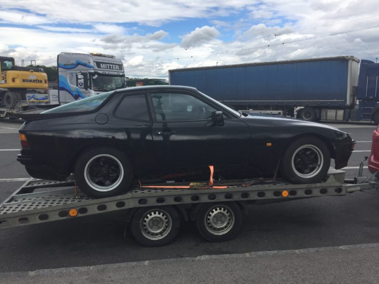
After my original Porsche 944 fan speed regulator (large resistor) burned down, I have been forced to find an alternative.
I could just buy a spare resistor from another car, but I find using PWM solution much better.
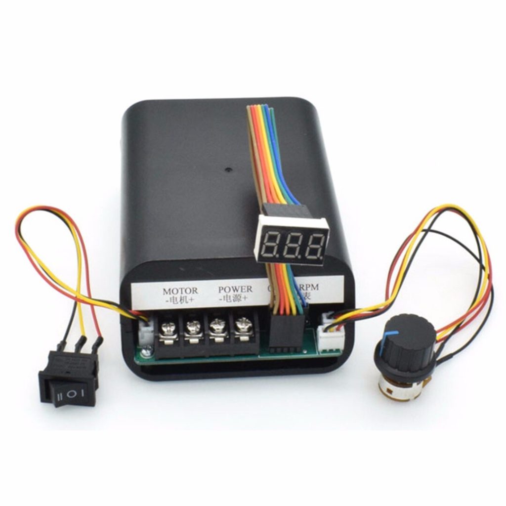
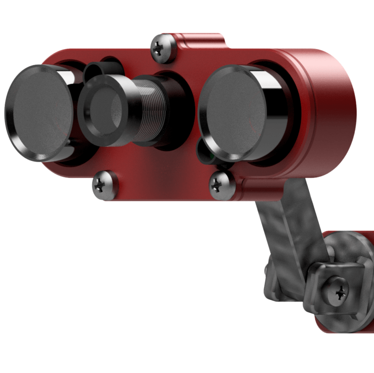
2. PWM fan speed regulator
This PWM regulator is well insulated inside a plastic case.
Small 5V fan inside the case provides better cooling for mosfets.
Potentiometer has ON/OFF switch.
With this three position switch you can choose between outlet-off-inlet states.
3-number 9-segment display is easily readable and can be called as 80’s typical display
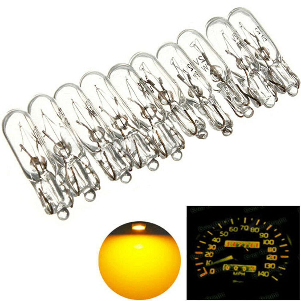
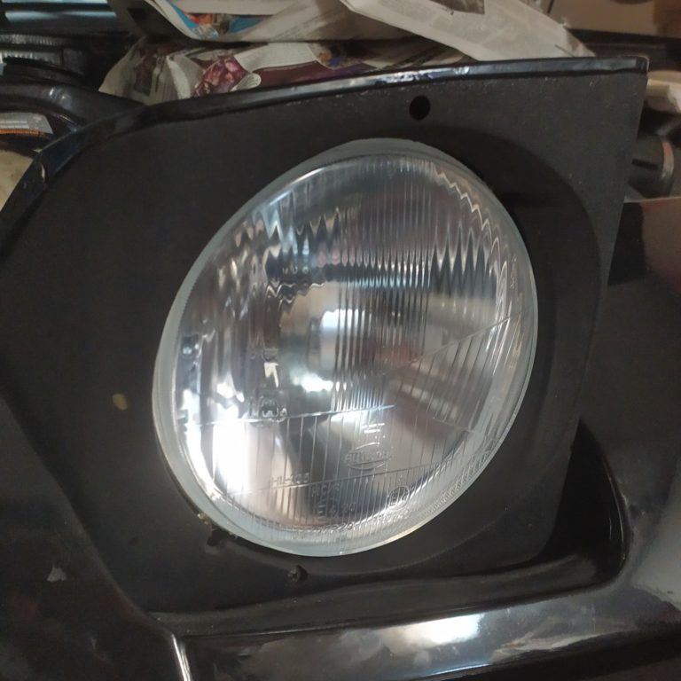
3. New light bulbs
You should buy new bulbs too while doing this upgrade. It is much easier to replace them when everything is disassembled.
T5, 12V, 2.0W
4. 12V to 5V converter
If you need more USB 5V ports for a dashcam or another reason, buy a 12V to 5V converter.
5V, 3A, 15W is more than enough.

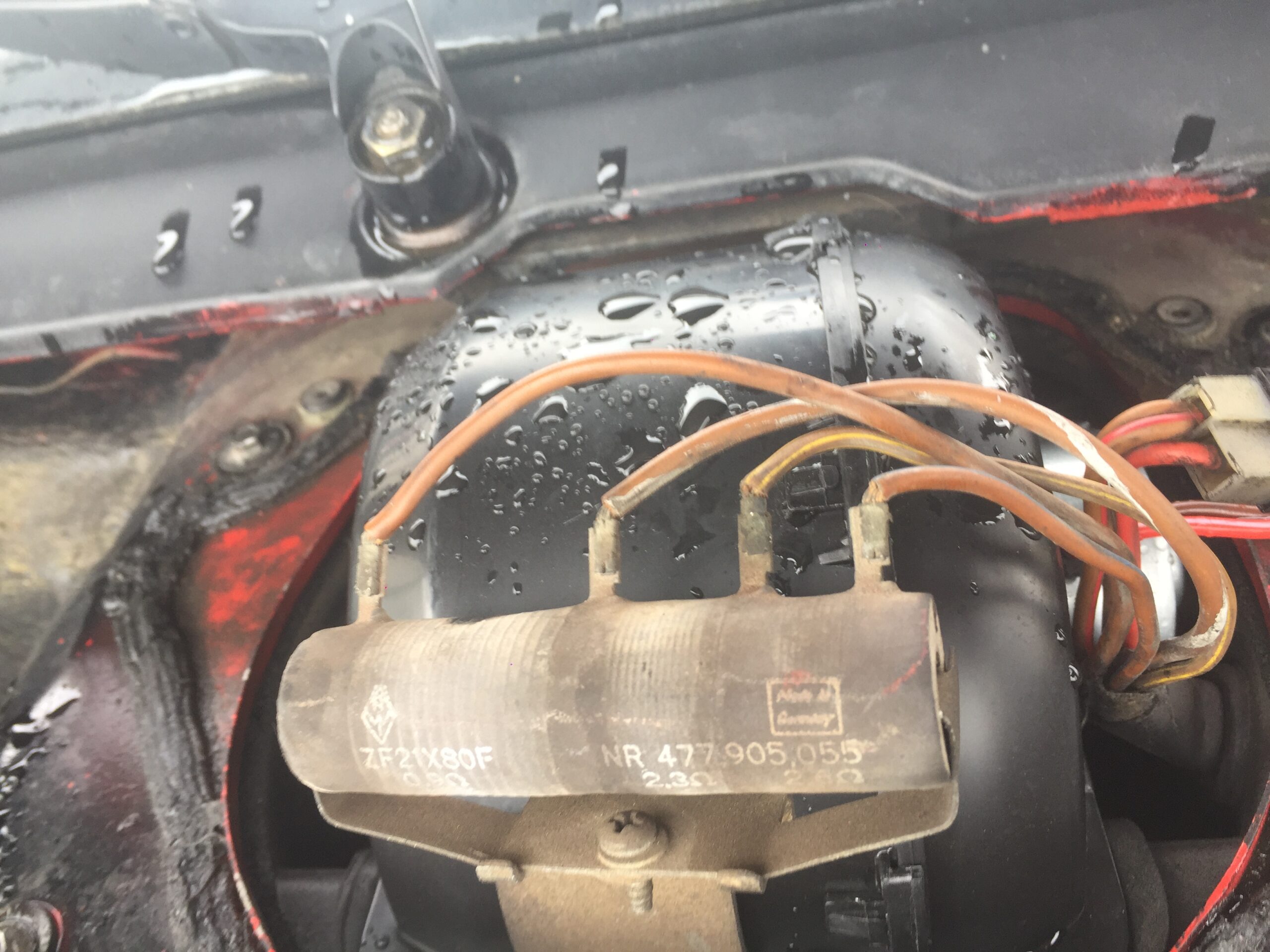
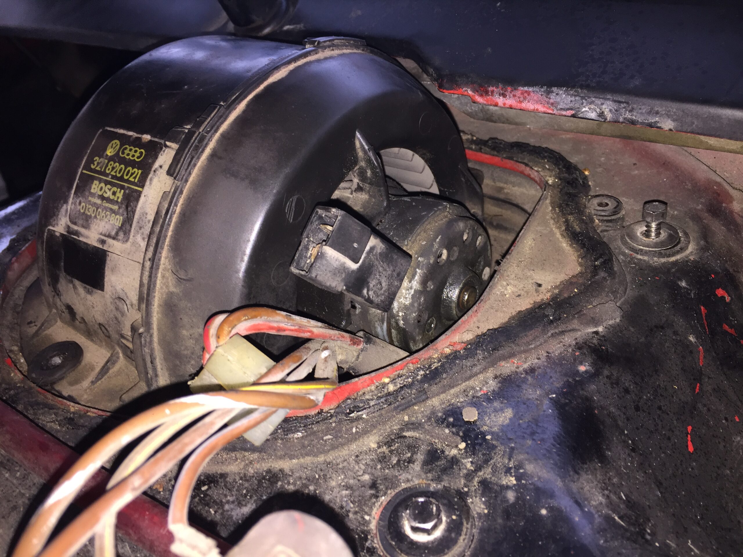
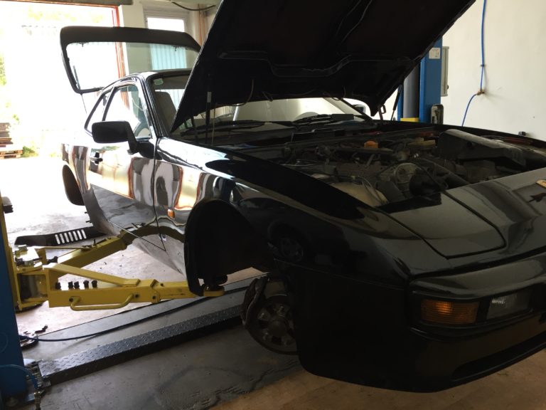
5. Disassembly
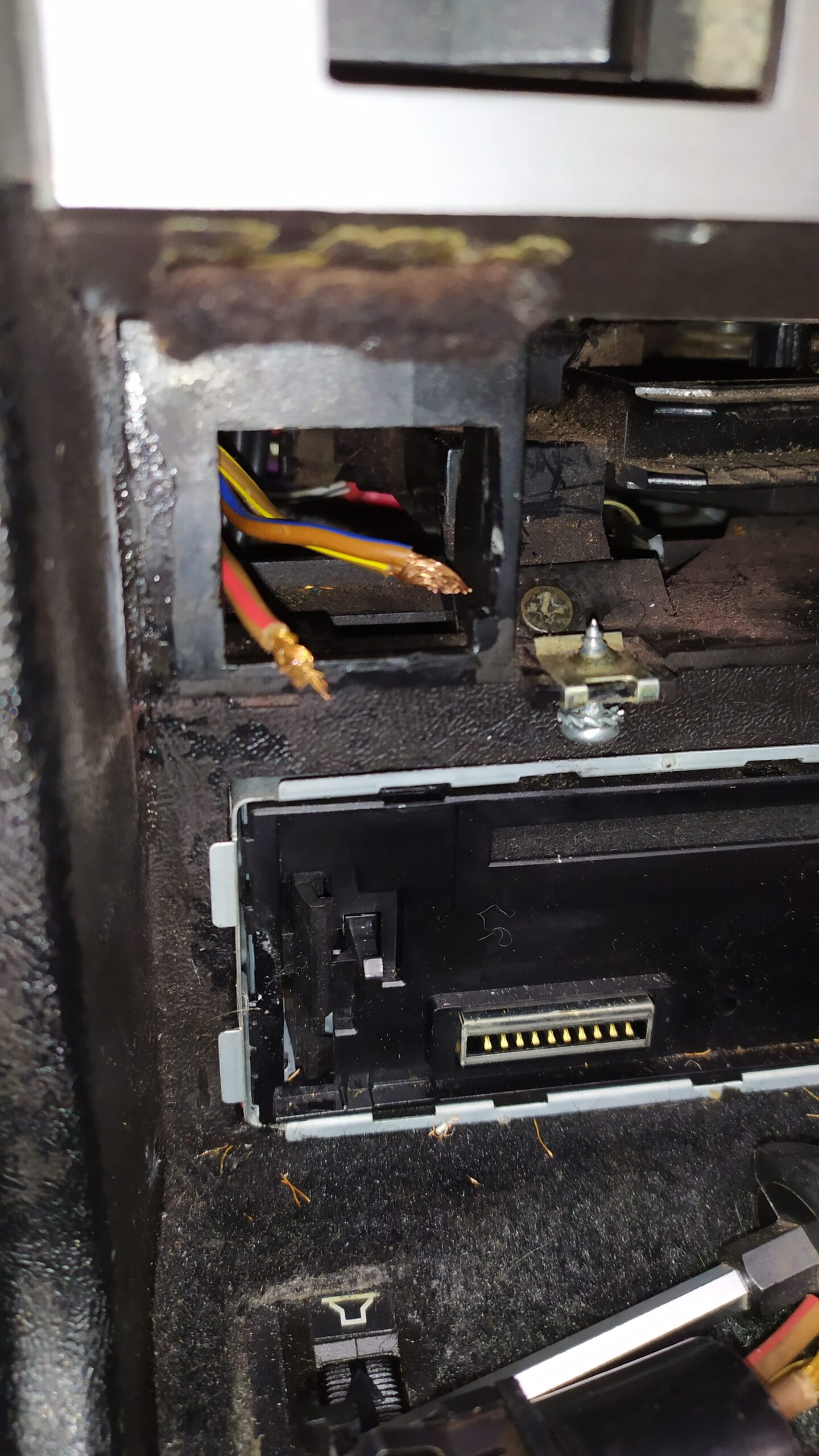
The first step is removing the old resistor.
Remove the fan cage.
Cut off 4 wires connected to the resistor (we will use them later).
Next step is disassembling heater control panel.
Take out all 3 levers and the knob.
There are two screws under the panel, unscrew them.
Remove the fan control panel.
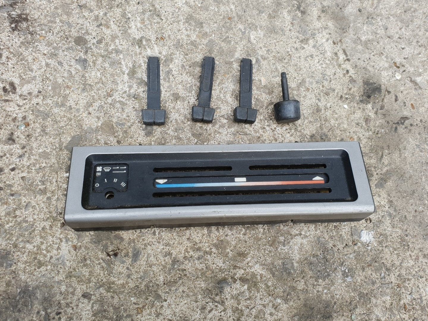
Remove the switch and cut all wires.
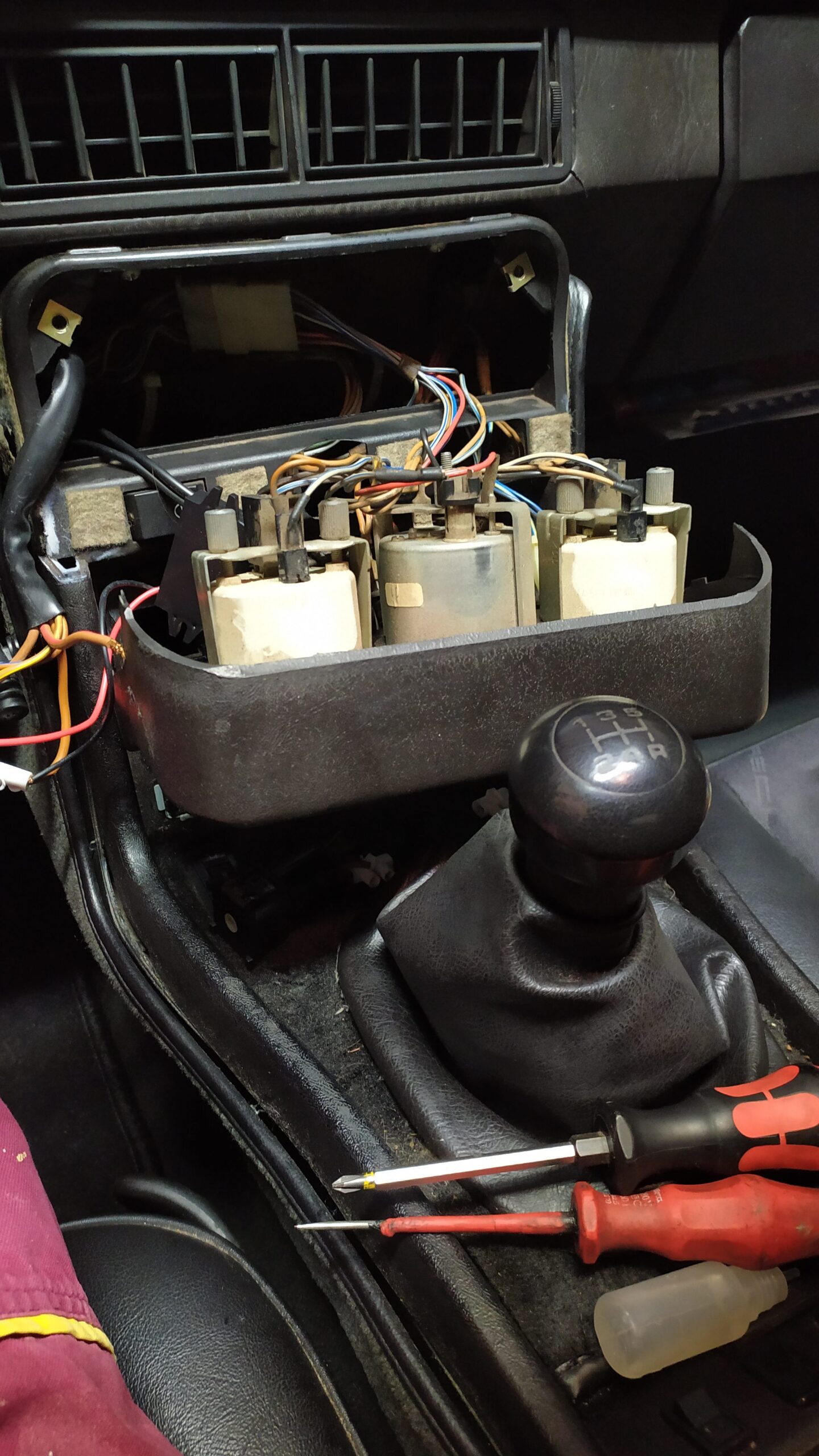
Unscrew two screws holding gauge panel at the top.
Insert a small flat screwdriver in the holes in the upper panel and detach it.
Look for a thick black cable harness and put it out
6. Modifications
Cut a hole with a dremel for the 3×8 segment display.
Use a drill and make a larger hole for potentiometer.

Apply a contact glue before inserting potentiometer and display in the panel.
Get a melt glue gun and add some of the glue on the display cables.

7. Assembly
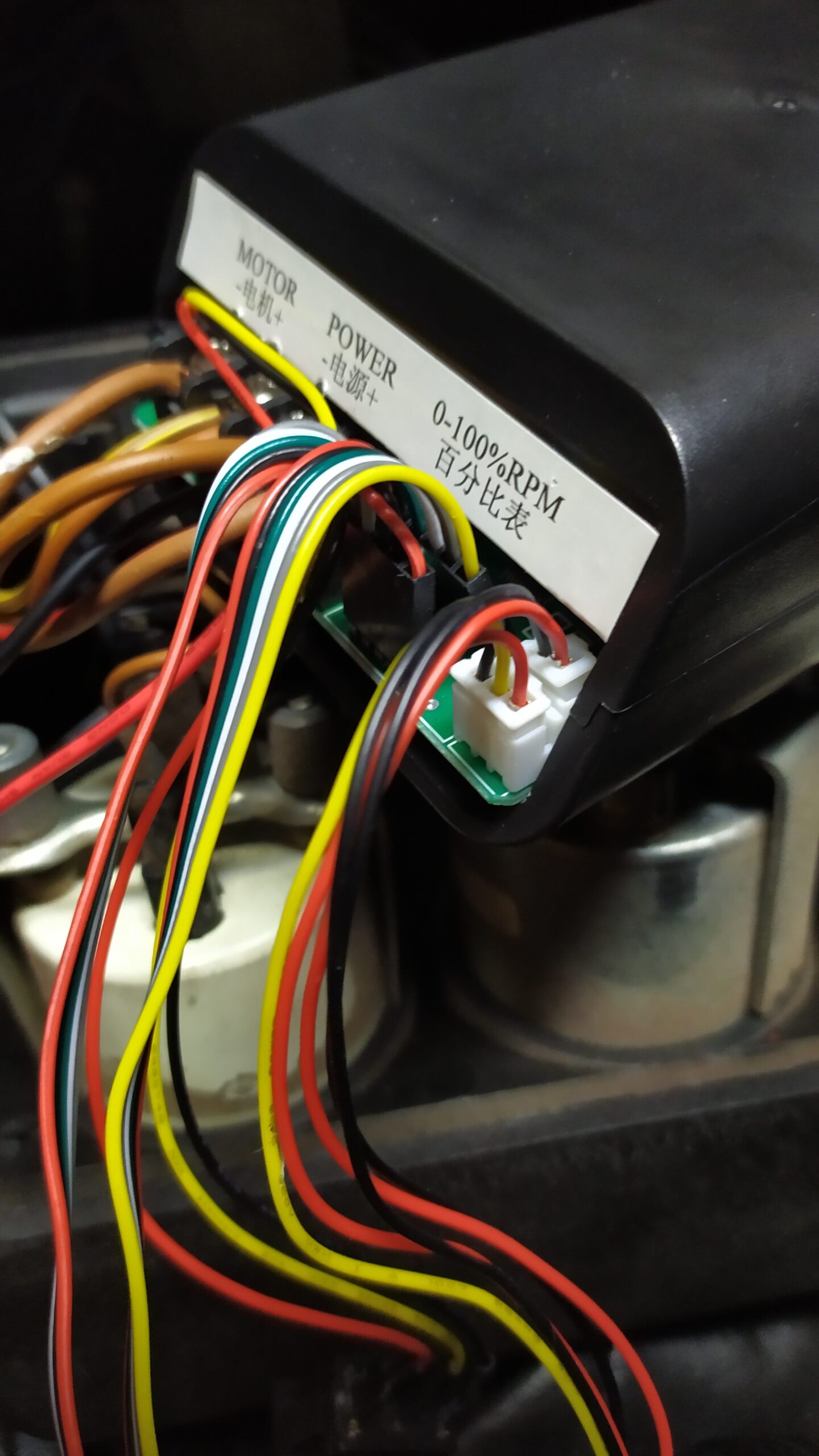
Put the cables through the hole after the old fan switch and connect them to the PWM unit.
You can use the old wires for an easier job.
Use a multimeter and find out which one of them is +12V which is GND, connect them to Power + and Power -.
If you are installing a power converter too, use the POWER connectors and plug it in too.
Use the remaining cables, the thickest (white stripe) as a Motor – and the remaining two as Motor +
Insert the PWM unit behind the panel and assemble the gauge and fan control panel.
good thank you paul
My 944 1983 model stuck on 3.